Fact: Weber Music Hall has a MIDI pedalboard. If memory serves it might be the Roland PK-6. Or maybe not.
Fact: It’s awesome.
Fact: I want one.
Fact: I don’t have the many many hundreds of dollars it would cost to spend on things like MIDI pedalboards. However, I do have several junked organs’ worth of components and a seeming excess of free time.
Therefore: A midi pedalboard! Building it was surprisingly simple and straightforward (that is, after a two hour diversion of several circuit rebuilds necessitated by the assumption that the circuit was not being built around a faulty shift register. Spoiler alert: it was!).
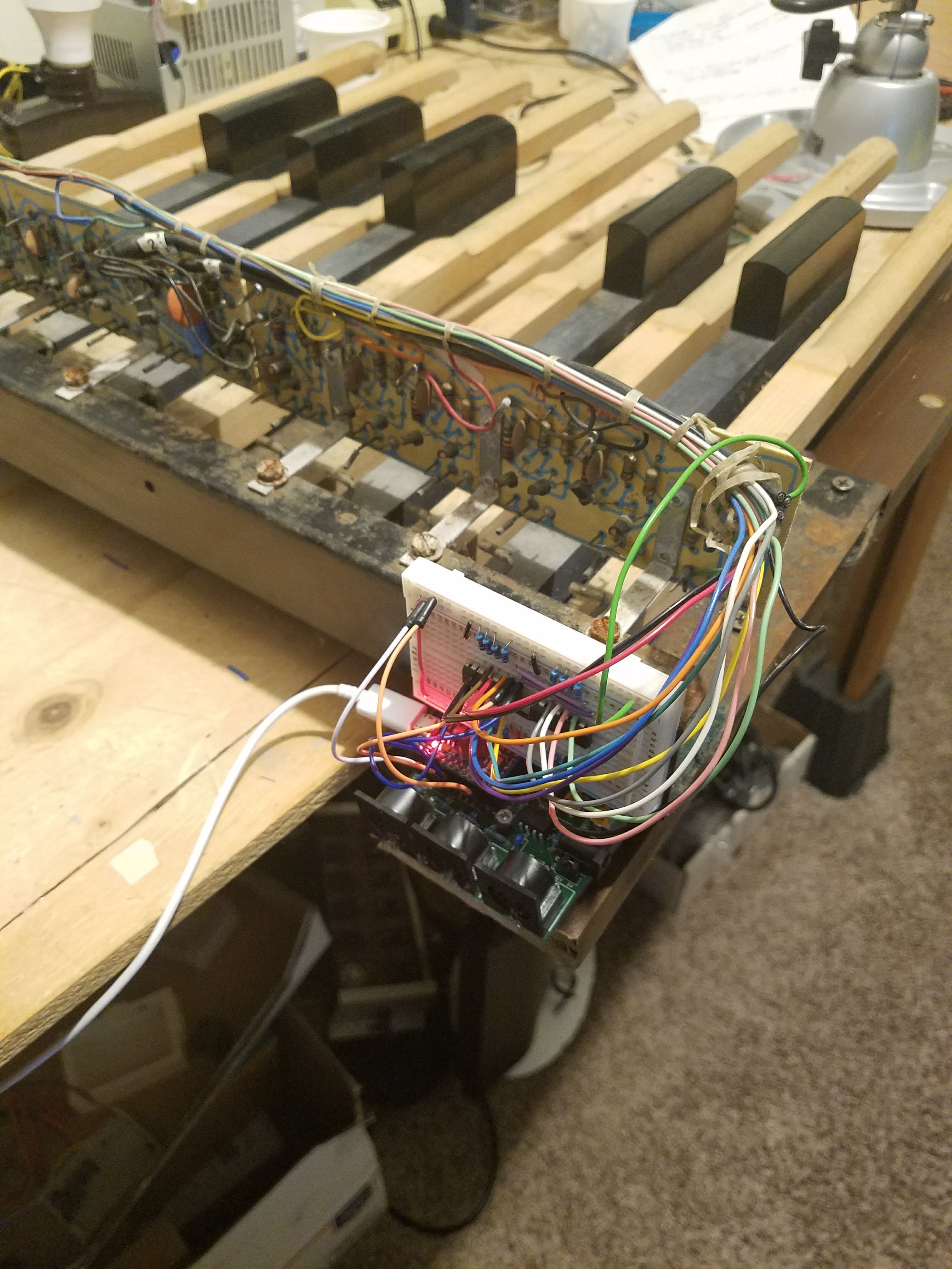
I pulled a pedalboard out of a less than perfectly functional Baldwin 125B organ (c. 1972) that was destined for the junkyard. The wiring is somewhat more complex than the straight-from-the-switches wiring I had been hoping for. So instead of figuring out how to make use of the preexisting circuitry (a lovely mix of transistors, resistors, and capacitors by the looks of it—more detail below), I just bypassed it by adding a jumper from the non-common side of the switch to the wire leading back to the main board.

This pedalboard has a range of an octave, C to C (I’m calling it C2–C3). This means I need 13 inputs. I only have 8 available from my board, so instead I’m using 74HC165 parallel-load shift registers for dealing with input. Each can handle eight inputs, so I need two. Add some pulldown resistors and power and here’s that board:
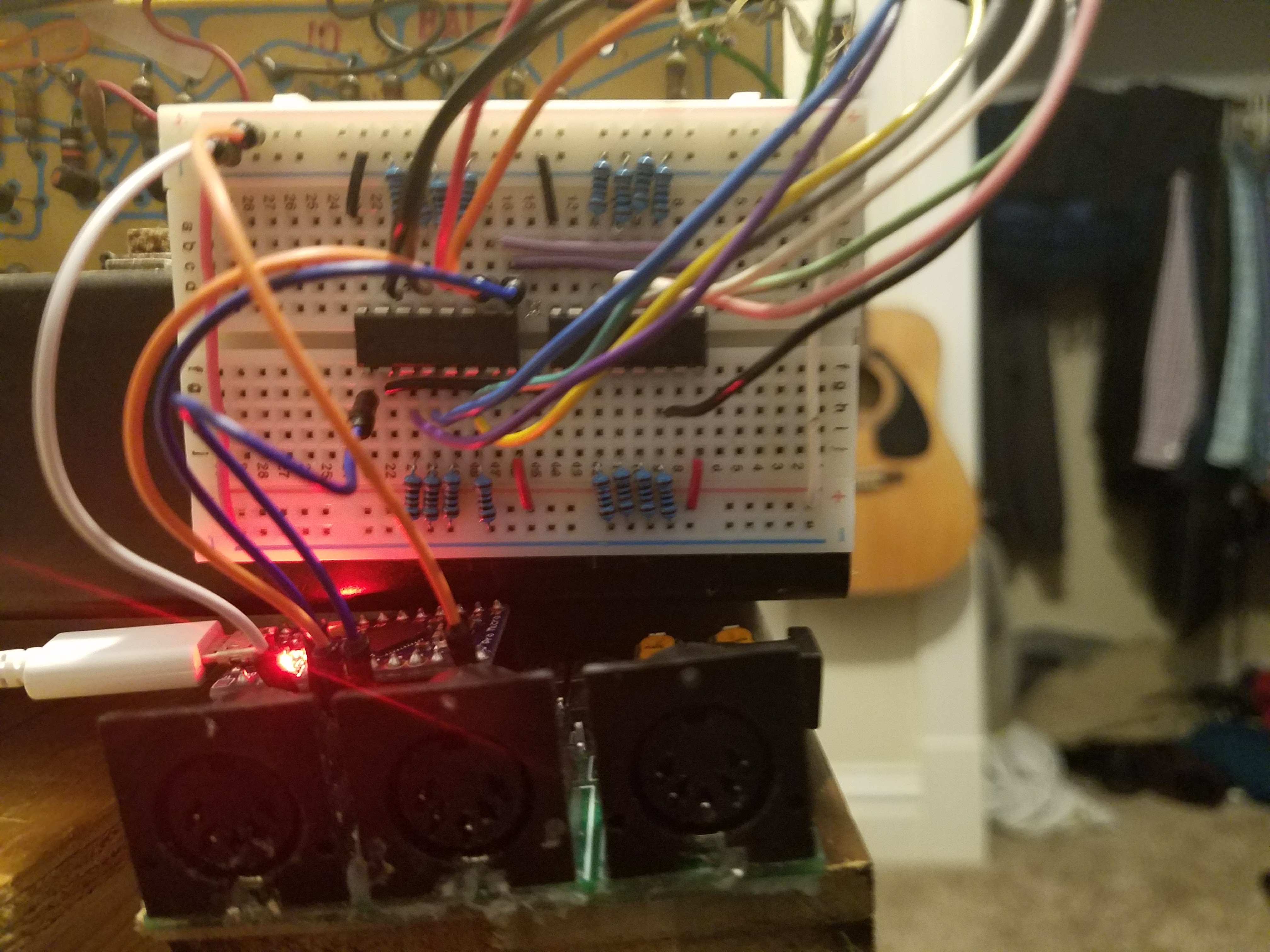
The Arduino board itself is a board I worked up for another project that was used fairly seamlessly for this project. I did run into a few issues though:
- No mounting holes. I ended up drilling a hole through a roughly quarter inch square unused space on the board and screwing it down through that, using a piece of heavy wire insulation as a spacer. It was…questionable, to say the least!
- I didn’t expose a VCC pin on the GPIO header, with the assumption that I’d just be connecting buttons shorting to ground and using internal pull-up resistors. Instead, I set the Arduino’s GPIO pin 9 as an output and drive it high, and then pull power from that. It’s a hack but works for a few milliamps.
- I wanted to have the buttons listen for input, but they’re not connected to interrupt-enabled pins which makes that a bit more complex, though not much. Just poor planning on my part!
- The MIDI ports aren’t connected to the hardware serial port. This just makes my configuration a bit more difficult, but I can still accomplish everything I need with Arduino’s SoftwareSerial.
None of these problems was insurmountable though, and here’s the final product, connected by USB to a computer running Hauptwerk: